Thus, suitable compensation circuits are required to compensate for the temperature variation of the channel amplifier performance over the specified temperature range for satellite transponders. The gain of the microwave amplifier modules, the attenuation of the PIN diode attenuators and the detected power level of the Schottky diode detector are all functions of temperature. The voltage V R1 level determines the gain of the channel amplifier in the fixed gain mode operation.

When the switch connects the attenuator AT1 to the other reference voltage V R1, the channel amplifier operates in the fixed gain mode. The switch position determines the mode of operation of the channel amplifier. The output of the DC amplifier is connected to the ALC attenuator AT1 through an analog switch. The other input of the differential amplifier is connected to the reference voltage V R2, which determines the output power level of the channel amplifier. This detected voltage is applied to one of the inputs of the differential DC amplifier. For the ALC function, the RF power is sampled after the amplifier A2 and detected by the detector diode. The attenuator AT2 is for adjusting the gain of the amplifier by up to –22 dB, in steps of –2 dB. The range of gain control of this attenuator is +15 to –5 dB over the nominal gain of 44 dB. The voltage variable attenuator AT1 is for the automatic gain control of the amplifier, depending on the input power level. The amplifier modules A1, A2 and A3 are used to meet the total gain requirement of the channel amplifier. The basic block schematic of the channel amplifier with ALC is shown in Figure 1.
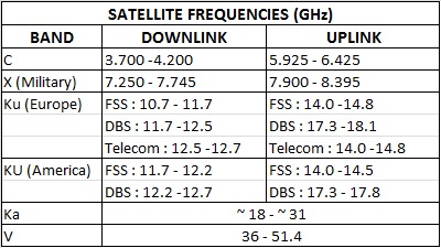
#KU BAND DOWNLINK FREQUENCY RANGE TRIAL#
A practical systematic procedure based on the measurement data instead of the conventional trial and error method is presented to determine the component values of the compensation networks. Thus, suitable compensation circuits 2–4 are included to compensate for the temperature variation of the channel amplifier’s performance over the required temperature range for satellite applications. It is known that the gain of the HEMT-based amplifier modules, the attenuation of the PIN diode attenuators and the detected power level of the Schottky diode detector are all functions of temperature. Another PIN diode attenuator is used for the adjustable step gain control. The attenuation of the attenuator varies according to the input power level so as to maintain the output power level of the channel amplifier constant. This detected voltage is amplified by a differential DC amplifier and applied to the control input of a variable PIN diode attenuator. 1 The amplifier contains a Schottky diode detector to detect the sampled RF power. In the ALC mode, the channel amplifier operates as a closed loop feedback system. The required gain of the amplifier is achieved by using three amplifier modules using PHEMT devices (CFY67-08). This amplifier has an adjustable gain control (22 dB) system to operate the final power amplifier in different back-off conditions in both modes of operation. In the fixed gain mode, the gain is 44 dB and in the ALC mode, the gain varies automatically from 39 to 59 dB depending upon the input power level. 1 This channel amplifier can operate in an ALC mode as well as in a fixed gain mode (FGM).


Thus, the ALC system also protects the final power amplifier against any accidental high power from the uplink. This article describes the design, development and characterization of a Ku-band channel amplifier with an automatic level control (ALC) system for spacecraft applications to control the input of the final power amplifier (TWTA or SSPA) according to the signal level arriving at the channel amplifier input.

Adaptive power control systems in the satellite transmitter and ground receiver can solve this problem. This may cause the signal level to fall below the sensitivity threshold level of the ground receiver a for specific BER performance. This signal level is further reduced by the downlink rain attenuation. The uplink rain attenuation causes a decrease in the signal level received at the satellite receiver, which leads to a decrease of the satellite transmitter power. In tropical regions, satellite communication links at Ku-band frequencies face excess up- and downlink paths loss due to rainfall.


 0 kommentar(er)
